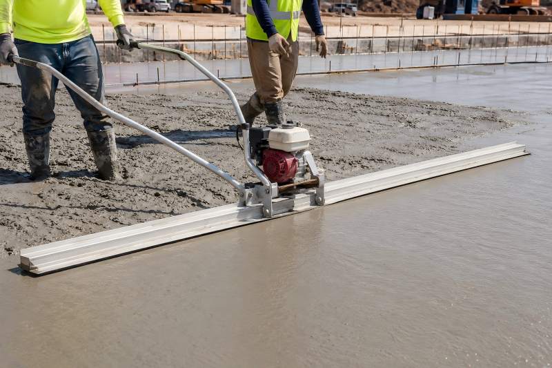
What Horsepower Does a Power Trowel Need for Different Concrete Applications?
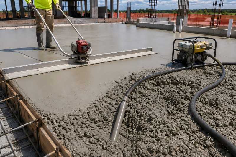
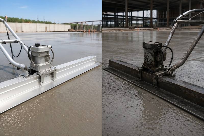
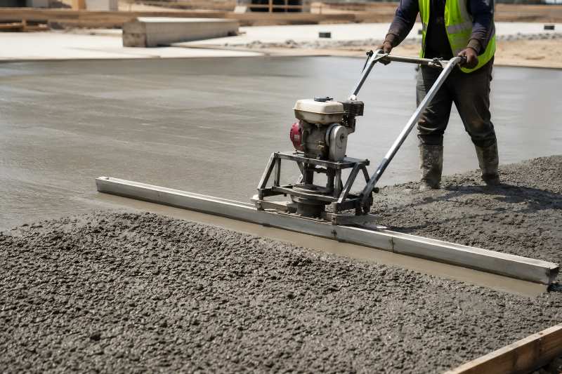
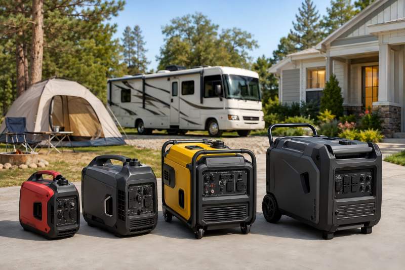
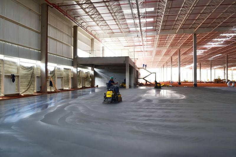
The required horsepower of a power trowel depends mainly on concrete application, working area, machine type, and finishing requirements. Small residential projects usually need 3–5 HP machines, while large industrial floors may require 30–60 HP ride-on models. How Does Horsepower Affect Power Trowel Performance? Horsepower directly affects the machine’s ability to rotate blades under different concrete conditions. During the early floating stage, concrete creates higher resistance because the surface is still soft and uneven. A more powerful engine allows the blades to maintain stable rotation speed and provides stronger performance when working on large or dense concrete slabs. Finishing results depend on multiple factors besides horsepower. A balanced design between engine output, machine weight, rotor size, and blade speed is essential. A lightweight power trowel with excessive horsepower may not transfer enough force to the concrete surface, while a heavy machine with insufficient power may struggle during operation. Factor Influence on Power Requirement Machine size Larger machines usually need higher horsepower Blade diameter Wider blades require more torque to maintain rotation Concrete hardness Harder surfaces create higher resistance Working area Large floors require continuous power output Machine weight Heavier machines need stronger engines for stable movement Recommended Horsepower Range for Different Power Trowel Types Power trowels are generally divided into walk-behind models and ride-on models. Each type serves different construction applications and requires different engine power levels. Power Trowel Type Typical Horsepower Range Recommended Applications Small Walk-Behind Power Trowel 3–5 HP Residential floors, sidewalks, small concrete slabs Standard Walk-Behind Power Trowel 5–9 HP Commercial floors, workshops, medium concrete areas Heavy-Duty Walk-Behind Power Trowel 9–13 HP Large slabs, industrial repair projects Single-Rotor Ride-On Power Trowel 20–35 HP Medium to large industrial floors Double-Rotor Ride-On Power Trowel 30–60 HP Warehouses, airports, large concrete surfaces Horsepower Requirements for Different Concrete Applications 1. Residential Concrete Floors and Small Projects Residential concrete applications usually include driveways, patios, garages, walkways, and small building foundations. These projects typically involve limited surface areas and do not require extremely high finishing speed. A small walk-behind power trowel with approximately 3–5 HP is usually sufficient. These machines provide good maneuverability and allow operators to finish narrow areas, corners, and irregular surfaces more easily. Recommended specifications: Parameter Recommended Range Engine power 3–5 HP Blade diameter 24–36 inches Machine type Walk-behind Typical working area Below 500 m² Advantages: Easy transportation and operation Suitable for small construction teams Lower fuel consumption Better control in limited spaces 2. Commercial Buildings and Small Industrial Floors Commercial projects such as retail stores, parking areas, workshops, and small warehouses usually require faster finishing speed and more consistent surface quality. 5–9 HP units combine strong performance with operational flexibility. These machines can handle larger areas while remaining easy to operate. Recommended specifications: Parameter Recommended Range Engine power 5–9 HP Blade diameter 36–46 inches Machine type Walk-behind Typical working area 500–2,000 m² For these applications, stable blade speed is important because uneven rotation may create surface marks or inconsistent finishing results. Choosing a machine with enough power reserve helps maintain performance throughout long working periods. 3. Large Industrial Floors and Warehouses Industrial warehouses, logistics centers, and manufacturing plants usually require high flatness and durability. Large-scale concrete flooring projects demand higher productivity and faster finishing performance. A heavy-duty walk-behind power trowel may require 9–13 HP, while ride-on models typically use 20 HP or more. The additional power allows the machine to operate larger rotors and apply greater finishing pressure. Recommended specifications: Parameter Recommended Range Engine power 20–40 HP Blade diameter 36–60 inches Machine type Ride-on power trowel Typical working area 2,000–10,000 m² Benefits of higher horsepower models: Faster concrete finishing speed Better performance on large slabs Reduced operator fatigue More consistent surface quality 4. Airports, Distribution Centers, and Large Infrastructure Projects Large infrastructure projects require equipment capable of continuous operation over extensive concrete surfaces. Airports, container yards, and distribution centers often involve strict requirements for floor flatness and surface durability. Double-rotor ride-on power trowels are commonly used for these applications. They usually require 30–60 HP depending on rotor size, machine weight, and operating conditions. Recommended specifications: Parameter Recommended Range Engine power 30–60 HP Blade diameter 60–90 inches total working width Machine type Double-rotor ride-on Working area Above 10,000 m² More power maintains stable operation under: Covering wide concrete areas Using larger blade systems Working on harder concrete surfaces Operating for extended periods How to Select Horsepower Based on Blade Size? Blade diameter is closely related to horsepower requirements. Large blades cover more area and demand higher torque. Blade Diameter Recommended Engine Power Typical Machine 24–30 inches 3–5 HP Small walk-behind trowel 36 inches 5–7 HP Standard walk-behind model 46 inches 7–10 HP Heavy-duty walk-behind model 60 inches 20–30 HP Single ride-on trowel 80+ inches 30–60 HP Double ride-on trowel Buyers should consider more than blade size when selecting the required horsepower. A properly matched combination of engine output, rotor design, and machine weight will provide better overall performance. Can Higher Horsepower Always Improve Concrete Finishing? Higher horsepower does not always mean better finishing results. A powerful engine can improve productivity, but excessive power may create unnecessary costs and operational challenges. For example, using a 40 HP ride-on power trowel on a small residential floor may reduce flexibility and increase operating expenses. On the other hand, using a 5 HP machine for a large warehouse floor may lead to slow progress and uneven finishing. The ideal horsepower should match the project requirements: Project Condition Recommended Choice Small area and detailed finishing Low horsepower walk-behind model Medium commercial flooring Medium horsepower walk-behind model Large industrial flooring High horsepower ride-on model Extremely large projects Double-rotor high horsepower model Choosing the correct horsepower is about finding the right balance between power, efficiency, and operating conditions. A properly matched power trowel can improve productivity, reduce labor costs, and deliver higher-quality concrete surfaces for different construction applications.